


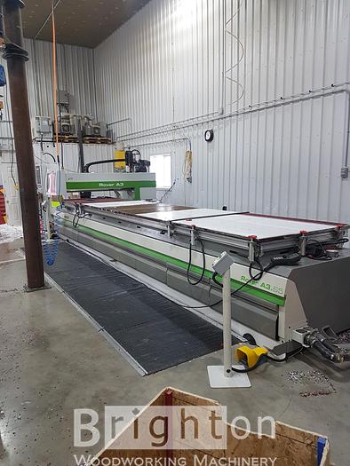
2007 Biesse Rover A 3.65 FT K2 CNC
2007 Biesse Rover A 3.65 FT K2 CNC
Location:Ontario, Canada
Description
2007 Rover A 3.65 FT K2 CNC Machine The Biesse Rover A 3.65FT represents technological advancements in machining centers designed for the processing of engineered and solid woods, plastics, non-ferrous metals, like aluminum and composite materials like Corian™.
Specifications
| Manufacturer | Biesse |
| Model | Rover A 3.65 FT K2 CNC |
| Year | 2007 |
| Condition | Used |
| Stock Number | BBM1990 |
| Quality | Very Good |
| Electrics | 380 volt with transformer for 600 volt if needed |
| Weight | 6160 lbs |
Additional Features
See pdf attachment below for complete specifications.
All specs to the best of our knowledge, but should be verified by the purchaser.
Working fields: X = 6450 mm; Y = 1290 mm; Z = 160 mm
Axes strokes: X = 6930 mm; Y = 1640 mm; Z = 200 mm
Structure
The machine base consists of a single component made up of thick electrowelded steel sheets, suitably strengthened in the most stressed areas.
The upright, mobile in the longitudinal direction (X axis) consists of a single electrowelded steel structural work: thick steel sheets and strengthening transversal elements allow to reduce to the minimum the distortions produced by the use of the machining center.
Movement of controlled axes
The mobile upright moves along the longitudinal axis (X axis) by pinion and rack, a solution BIESSE has used for twenty years which grants acceleration parameters and movement speeds greater than those obtained through a ball screw.
Both rack and pinions are in accuracy class nr. 6 (DIN 3962 norm).
The operating unit moves in the transversal direction (Y axis) and vertical direction (Z axis), with a relatively limited travel, by means of ball screw and preloaded nut for backlash compensation and repeatability in positioning precision. The motorization is transmitted to the screw by means of a toothed belt.
The ball screws are in accuracy class ISO 5.
Motorization of controlled axes
BIESSE uses Brushless motors, controlled by digital drives.
DIGITAL interface between numerical control and axes drives.
The digital system Mechatrolink grants:
-Greater machining speed, since the tool route is partly controlled by the drive instead of the numerical control;
-High working precision, thanks to faster data processing;
-High reliability, thanks to a reduced wiring system which eliminates electrical interferences typical of analogic systems;
-Reduced machine stops and downtime, thanks to the error diagnostics with explanatory messages displayed directly on the N.C.
Automatic lubrication system
At each time interval, programmable through the numerical control, the pump automatically sends the lubricant to the following machine components, with no machine downtime and no operator's intervention:
-X axis: 4 sliding blocks of the linear guides and rack (in two points)
-Y axis: 4 sliding blocks of the linear guides and ball screw nut
- Z axis: 4 sliding blocks of the linear guides and ball screw nut
- Slots: 2 sliding blocks of the linear guide
When the quantity of lubricant in the tank is below the minimum a message appears on the n.c. screen.
FT Work Table
The work table is in stratified phenolic, it includes a vacuum clamping system for the pieces and has a 30mm pitch grid for the rapid placement of the holding device or of the standard clamping modules. The entire work table is covered with vacuum channels ( D = 10 mm) with 150 mm x 120 mm center distance, and is equipped with patented plugs for a quick removal. It can be configured based on need (pitch 30 mm) with M8 threaded inserts for jig installation or other clamping equipment.
6 back stops + 6 front stops equipped with pneumatic system and sensors.
Pneumatic lowering controlled by the n.c.
4 side stops equipped with pneumatic system and sensors.
Pneumatic lowering controlled by the n.c.
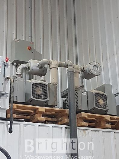
Vacuum tank
Integrated in the machine base, it grants a constant and high level of vacuum during initial locking operations and in case of vacuum leakages due to the machining of porous material.
Vacuum system for 3 300 m3/h pumps
The system supplies the vacuum to the work area, allowing the locking of pieces.
It includes:
-Electric prearrangement for the connection of 3 vacuum pumps;
-Electrovalves for system feeding and control;
-Pipes for vacuum feeding;
-Digital vacuostats for the differentiation of the minimum vacuum safety levels during the flattening of the spoil board or the machining of pieces;
-2 work areas.
2 300 m3/h vacuum pumps
- Oil working
-Flow rate: 300 m3/h at 50 Hz and 360 m3/h at 60 Hz
WORKING UNITS
7212006
12 kW (16.1 HP) Electrospindle with HSK-F63 adaptor, air cooled
The innovative 12 kW (16.1 HP) Electrospindle, HSK-F63 adaptor, air cooled on the Rover machines is manufactured by HSD (High Speed Development), a Biesse Group company.
Benefits for the customer of the HSD technology:
INCREASED PRODUCTIVITY with:
- 7.5 kW (10.2 HP)/7,000 rpm in S1 duty
- 10 kW (13.6 HP)/from 12,000 to 15,000 rpm in S1 duty
- 12 kW (16.1 HP)/12,000 rpm in S6 duty
- Efficient cooling system.
PRECISION AND QUALITY MACHINING
- The electrospindles on the Rover machining centers are attached directly at Z-axis carriage and extremely close to the Y-axis beam. This solution guarantees superior rigidity and is completely
unaffected by the thermal expansions always present when
the
electrospindles are attached to the boring block effecting
precision.
- Pneumatic stroke is on a prismatic linear guide for
maximum strength and precision
HIGH PERFORMANCES AND FLEXIBILITY with
- Programmable rotation speeds from 1,000 to 24,000 rpm
- RH and LH programmable rotation
- Dust hood has 6 pos., CNC adjusted for optimum dust collection in any working conditions.
REDUCED MAINTANANCE with
- Cartridge construction which allow for easy core replacement.
- Ceramic bearings, which are less susceptible to thermal elasticity than steel bearings, thus providing increased life
Air Nozzle
Flange for the assembly of aggregates on the electrospindle
The flange to be installed on the electrospindle is equipped with 4 conical seats for aggregate reference each 90°.
Prearrangement for operating device with 360° interpolation and gear transmission.
Non-stop rotation of the "C" axis through 360° in one second.-
Boring head BH 21 L
Working unit equipped with 21 independent tools for single and multiple borings on 5 panel sides.
The spindles have an alternate Rh/Lh rotation and move by means of precision ground helical teeth which grant maximum operating accuracy and silence.
The head is composed of:
- 14 independent vertical spindles at a centerdistance of 32 mm, 7 of which are placed along X and 7 along Y;
-3 independent horizontal spindles with double outlet at a centerdistance of 32 mm, 3 of which is placed along X and 1 along Y;
- 120mm saw blade for grooves in X direction only
The head is moved by 1 motor controlled by inverter (motor power 1.7 kW at 2800 rpm - 3 kW at 6000 rpm): the spindle rotation speed can be adjusted up to 6000 rpm, to perform quick boring cycles and therefore reduce the working time. In addition, it is possible to choose the rotation speed according to the tools employed and the material type.
Revolving tool changer with 18 places
Installed on the X carriage, it allows to have up to 18 tools and aggregates always available where required on the machine, therefore reducing the tool change time.
Main specifications:
-Tool grippers centerdistance: 94 mm;
-Tools which can be stored: 18 tools with a diameter of 90 mm;
-Aggregates: see tool-changer layout;
-Max. Tool diameter: 240 mm in alternate mode;
-Max. Tool length: 265 mm - see tool-changer layout;
-Max. Weight of tool or aggregate + tool: 8 kg;
-Max. Total weight: 54 kg.
Controls on remote keyboard
Remote keyboard with potentiometer for the manual control of the axes speed, and with emergency push-button.
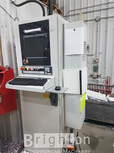
Numerical Control
PC-based control system XP600.
Thanks to the new Biesse technology WRT (Windows Real Time), which increases the performances of Windows XP by making it work in real time, the machine is controlled directly by the PC, and any other hardware component becomes unnecessary.
Since the software that controls the machine runs directly on a personal computer and not on a dedicated hardware device, the system architecture is greatly simplified, grants greater performance and reliability.
BIESSEWORKS - Advanced programming system - machine version and office version. ( 1 Machine Key & 1 Office Key)
The graphic interface, fully compatible with the Windows standard, grants the following functions:
-Assisted graphic editor for the programming of boring, cutting and routing operations. The Editor handles multiple documents, so it is easy to copy a machining operation from one document to another through the Windows copy/paste functions;
-Interactive graphic views with zoom function. It is possible to select machining operations graphically and modify their technological parameters;
-Automatic optimization of borings, tool changes and tool routes;
- Possibility of defining the work sequence with the mouse, by selecting the workings from a list;
- Parametric programming, with the possibility of specifying the values of the parameters when a parametric program is run;
-Import of files from CAD and other outside software systems in DXF and CID3 format. DXF files can be purely geometric or can contain all the technological parameters necessary for machining;
-Conversion of groups of DXF and CID3 files with no need of importing them one by one (batch-run module);
-Possibility of executing DXF and CID3 files directly;
- Graphic configuration of machine data;
- Tool database with search filters helping tool selection. It is possible to associate a shaped profile in DXF to every tool and automatically generate its 3D representation;
-Mouse selection for operating units and tool changers tooling operations;
-Graphic set-up of panel supports: immediate detection of tool collisions with piece locking devices, automatic generation of the set-up on symmetric or translated origins and possibility of defining the rotation of the vacuum modules.
BiesseWorks Advanced also includes:
- Guided creation of customized parametric macros, with the possibility of recalling them through icons which can be included in the software interface;
- 3D simulation of the tool path, to allow the operator to check on the PC the real situation on-board the machine, thus detecting of any errors in advance;
- Approximate calculation of machining time;
-Parametric programming of the work area: by changing the parameters the programs automatically adjust both the workings and the positioning of the elements on the work area;
-Automatic pocketing of any shape with the possibility of leaving islands in relief at different depths;
-Text engraving using Windows True Type Fonts;
- Possibility of defining rotated or circular faces in addition to the six standard faces available in the editor. Programming for these faces is entirely similar to programming the standard faces;
- Programming of the chip deflector aggregate
BIESSE NEST Module
Entry-level software module for nested-based manufacturing
This module allows operators to create a project for the automatic positioning of the pieces to be
produced on rough material sheets, so as to minimize material waste and optimize the respective work programs. The module produces a series of BiesseWorks programs (BPP).
A BiesseNest project allows the import of:
- BiesseWorks (BPP) programs, even parametric, with the possibility of modifying the values of the parameters
- CID3 files
- DXF drawings
With BiesseNest panels can have any type of shape. The workings are arranged so as to minimize tool change and machine movement, and to perform through workings last.
BiesseNest can print labels and drawings:
• The label for each produced piece following the machining order, sheet by sheet
- The drawing of the cutting list for each rough material sheet with identification methods helping users stick the labels on the right pieces
The project can be defined manually within BiesseNest or it can be imported, in the following formats:
- formatted text file created by an external file or exported from an Excel worksheet
- XML file exported by the software Optiplanning (Selco)
Desktop Personal Computer
Main technical specifications:
-CPU Intel Celeron D 2,8 GHz or superior; 512 MB RAM memory; 40 GB hard disk
- 15" LCD; keyboard; mouse; cd-rom reader
- Parallel port; serial port RS-232; USB ports; Ethernet card for network connection to an office pc
These technical specifications may be subject to updates
Since the personal computer controls the processes BIESSE does not allow the installation of additional non-authorized software, under penalty of losing the guarantee.
Statistics
Machine statistics, capable of collecting general information on machine performances and production, in order to record reliability over time and productivity. Customers can choose directly the events to be recorded, examples are: machine set-up, control of workings, authorized pauses, lubrication cycles, etc…
Teleservice
It allows an immediate and direct access to the machine numerical control via modem. This way it is possible to check machine data, user programs, input/output signals and system variables, and to install software updates, therefore granting:
- Real-time answers
- Quick problem solving
- Strong reduction of machine downtime
-Real-time software updates
The teleservice support is free of charge for the whole warranty period.
Air conditioner for electric cabinet
It allows:
- The perfect working of all the electronic components included in the electric cabinet, even at very high temperatures, up to 40°C (104°F);
-A dust-free environment, since there are no aeration fans.
Inverter
Static frequency converter for electrospindles with power up to 14 kW.
Safety devices
- 2 front safety mats equipped with control unit providing safety measures;
- Back and side fencing;
- Emergency rope placed in front of the machine;
- Sound-absorbing cover for the operating unit, made up of structural and protective plates, 5 layers of overlapping plastic strips (for a total thickness of 15 mm), and a transparent panel in crushproof polycarbonate allowing operators to work in total safety since it grants maximum visibility;
-Emergency button positioned on the n.c.;
- Emergency button positioned on the remote keyboard;
- The controls included in the remote control panel allow operators to work with the machine in total safety (emergency stop, tool feed speed adjustment ...).
Emergency recovery procedure
This function allows operators to restart an interrupted working due to a machine emergency stop. The program restarts exactly from where it was interrupted, by following a specific procedure.
Tool route calculation function
The NC memorizes the meters covered by each routing tool up to a maximum allowed distance. When this distance is reached a warning message is displayed on the screen. This message will be displayed each time a tool reaches the maximum allowed distance while working.
A hardware port allows the connection of an external device (for instance a flashing light or a siren) which will be activated when the message appears on the screen.
49720 Autotransformer for voltage different from 380 V/50 Hz.
Technical Data
- Electrical: 39 kVA
-Compressed Air
- Pressure 7.5 bar (105 PSI)
- Air consumption 400 NL/Min (14 CFM)
- Dust collection
- Chip extraction socket diameter 250 mm
- Chip extraction air consumption: 5300 m3/h (3125 CFM)
- Air speed at the manifold 30 m/sec (99 foot/sec)
- Static Pressure 3000 Pa (12 inch water)